Pre-and Post-lay Trenching of a pipeline (2025-2026)
Scanmudring delivered pipeline and umbilical trenching, pipeline lowering and selected backfilling for a major offshore gas development in Angola. Combining SCANCFE 9000 and Scanmachine 40Te, the campaign adapted to hard clay, limestone, consolidated coral and rapidly shifting sand through specialised tooling and survey-guided adjustments.
The development required pre- and post-lay protection of subsea infrastructure supporting a major offshore gas project. The wider offshore system included unmanned well headfacilities and an export pipeline connecting the offshore production area to an onshore treatment facility. Scanmudring’s role was delivered in two phases: pre-lay trenching to prepare the seabed for pipeline laying, followed by post-lay trenching, pipeline lowering and selected mechanical backfilling across the pipeline and umbilical scopes.
In Phase 1, the hardest seabed sections identified along the 26-inch route were pre-trenched ahead of pipelay. In Phase 2, Scanmudring’s scope comprised trenching 6 km of 16-inch pipeline, 38 km of 26-inch pipeline with a 4-inch fibre-optic cable piggyback, and 6.3 km of umbilical. The contracted work also included mechanical backfilling on selected sections of the 26-inch pipeline.
Planning Phase
For Phase 1, Scanmachine 40Te was configured with project-specific rock chain cutters, excavation buckets and suction nozzles with tilt for the hardest seabed sections. In Phase 2, the campaign required one excavation spread to support several distinct scopes across two offshore construction vessels. One vessel was used for the 16-inch pipeline, while the second supported the 26-inch pipeline, umbilical trenching and mechanical backfilling.
The combination of SCANCFE 9000 and Scanmachine 40Te offers the flexibility of two tools supported by a single topside spread and just one crew. Scanmachine 40Te handles the harder areas, while SCANCFE 9000 excavates the remaining material suited to controlled-flow excavation. This allows the team to match the tool to different seabed materials without requiring separate topside spreads or crews.
Planning covered recurring technical meetings, vessel interfaces, project-specific mobilisation and operating procedures, wet testing, survey integration and preparation of the three-dimensional monitoring environment. A mechanical excavation tool was evaluated as a contingency for very hard seabed, but was not deployed after the client selected concrete mattresses for the remaining non-removable sections.
Challenges
Shallow water, no visibility and strong currents, including riptides, during pre-lay trenching.
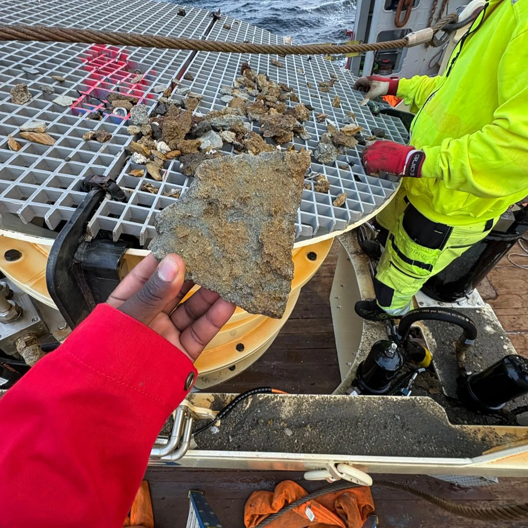
Significant variation in seabed composition and hardness, from hard clay, limestone and large rocks in Phase 1 to consolidated coral and sandstone in Phase 2 that exceeded the effective capability of controlled-flow excavation in some sections.
Rapid natural backfill in loose sand, limiting the time available for the pipeline to settle.
A 26-inch pipeline with a 4-inch fibre-optic cable piggyback requiring controlled trenching and verified cover.
Repeated breakage of suction and water-supply hoses in the mixed Phase 1 seabed.
Specific tooling
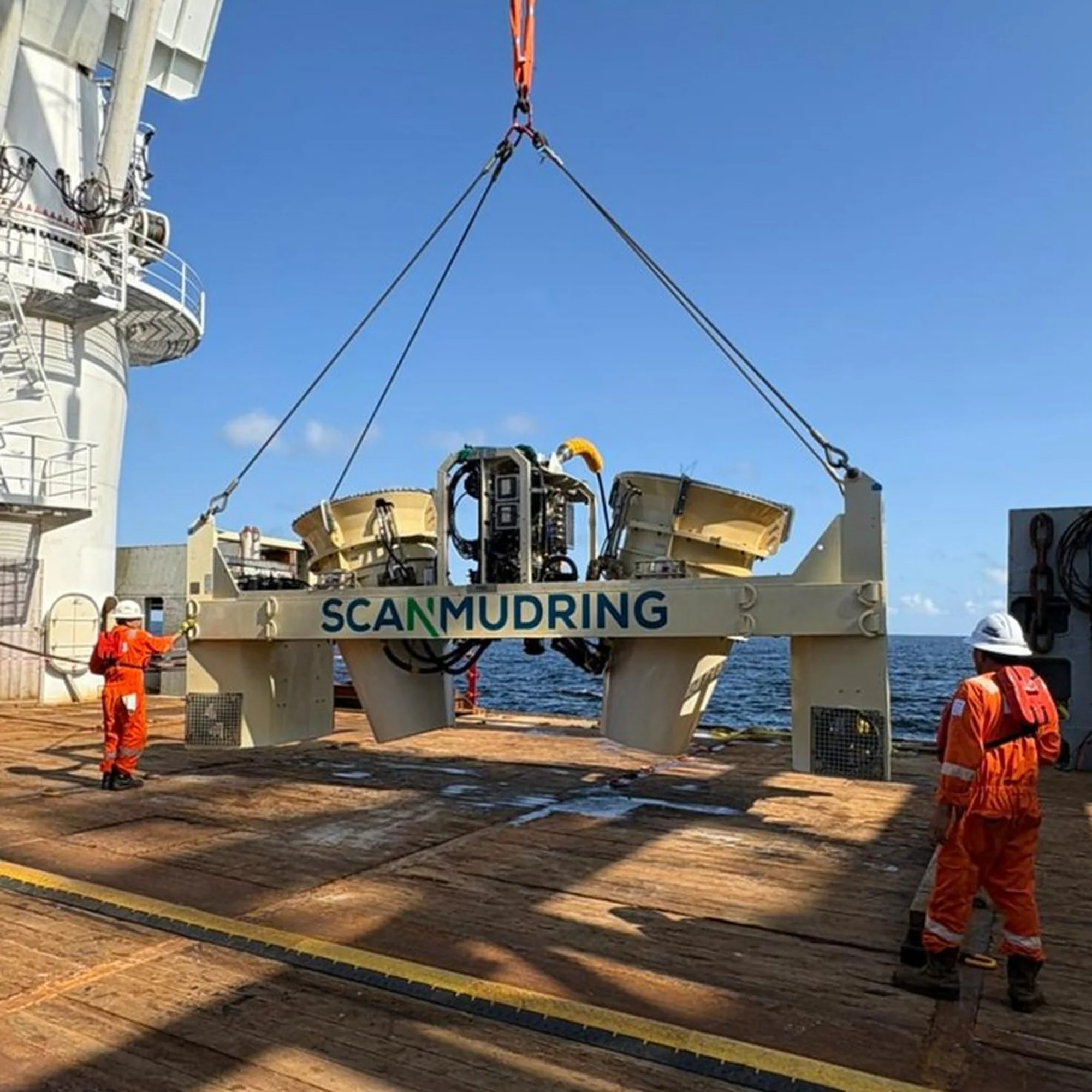
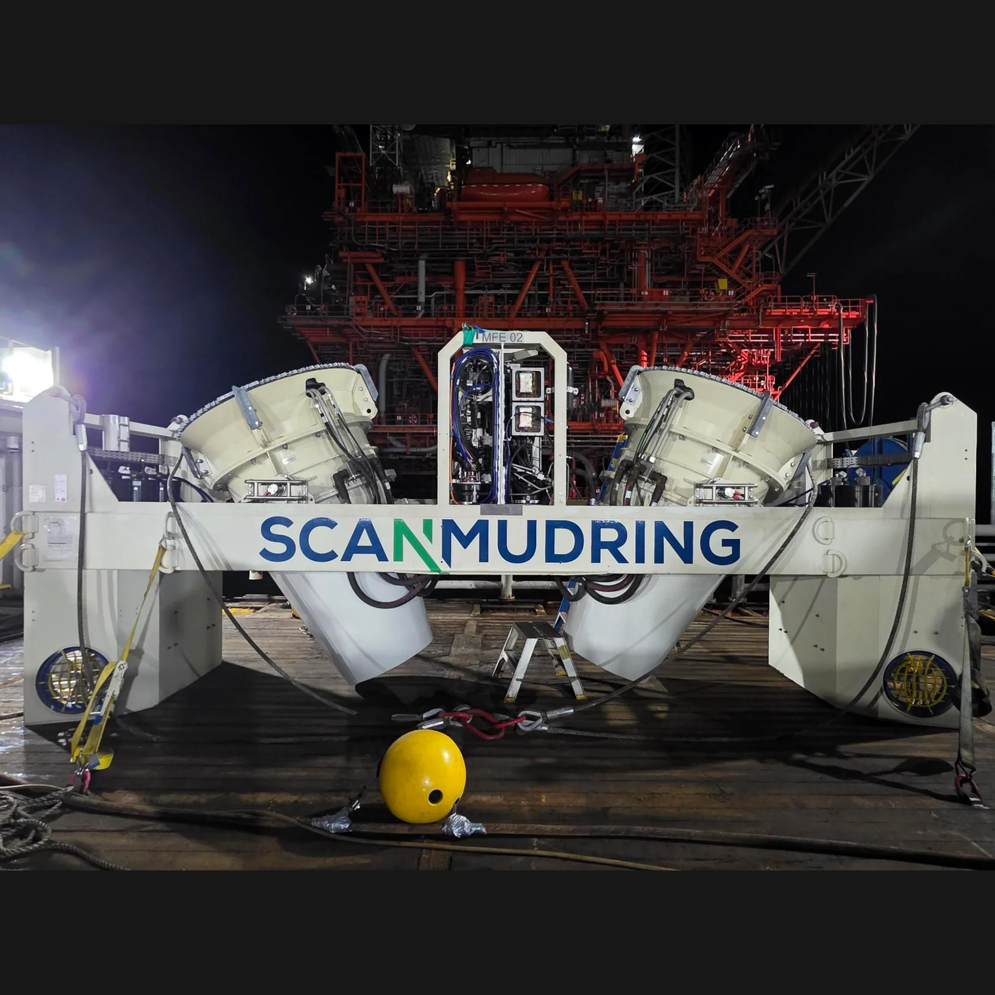
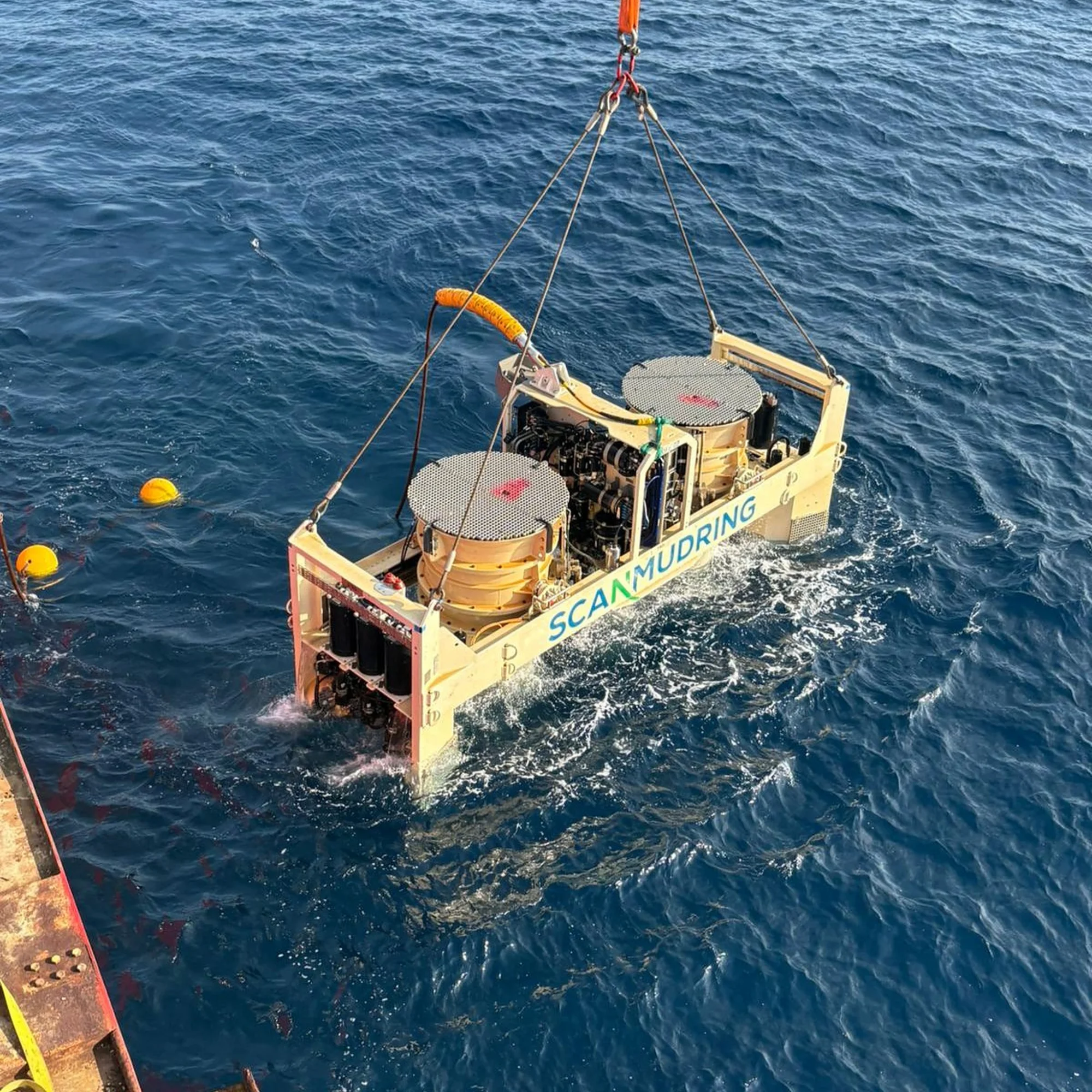
SCANCFE 9000 controlled-flow excavation spread, used throughout Phase 2.
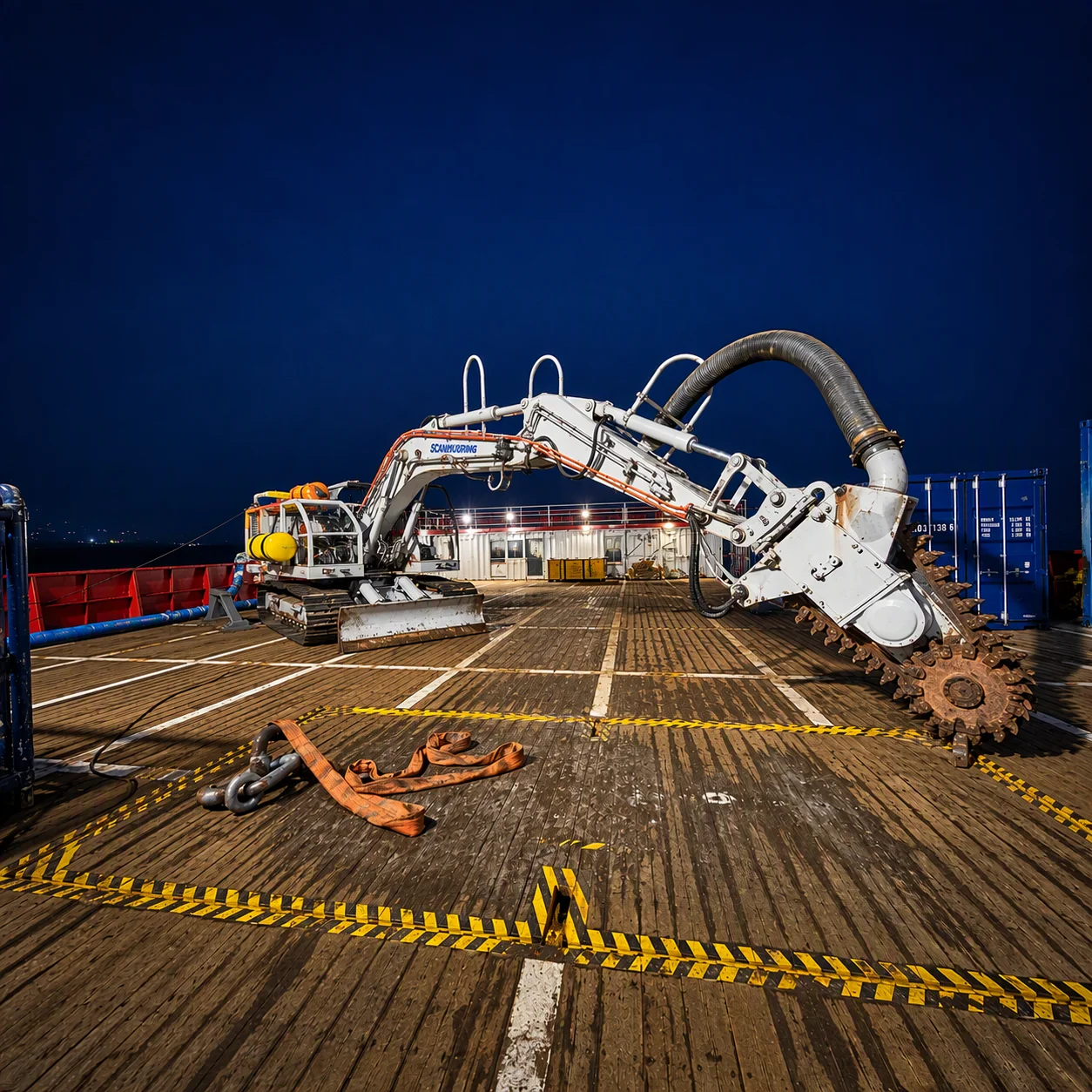
Scanmachine 40Te with rock chain cutters, suction nozzles and excavation buckets for Phase 1; the bucket with water-jet supply proved most effective.
Interchangeable 0.6 m, 0.8 m and 1.0 m outlet nozzles with tilt and thruster adjustments for precise targeting.
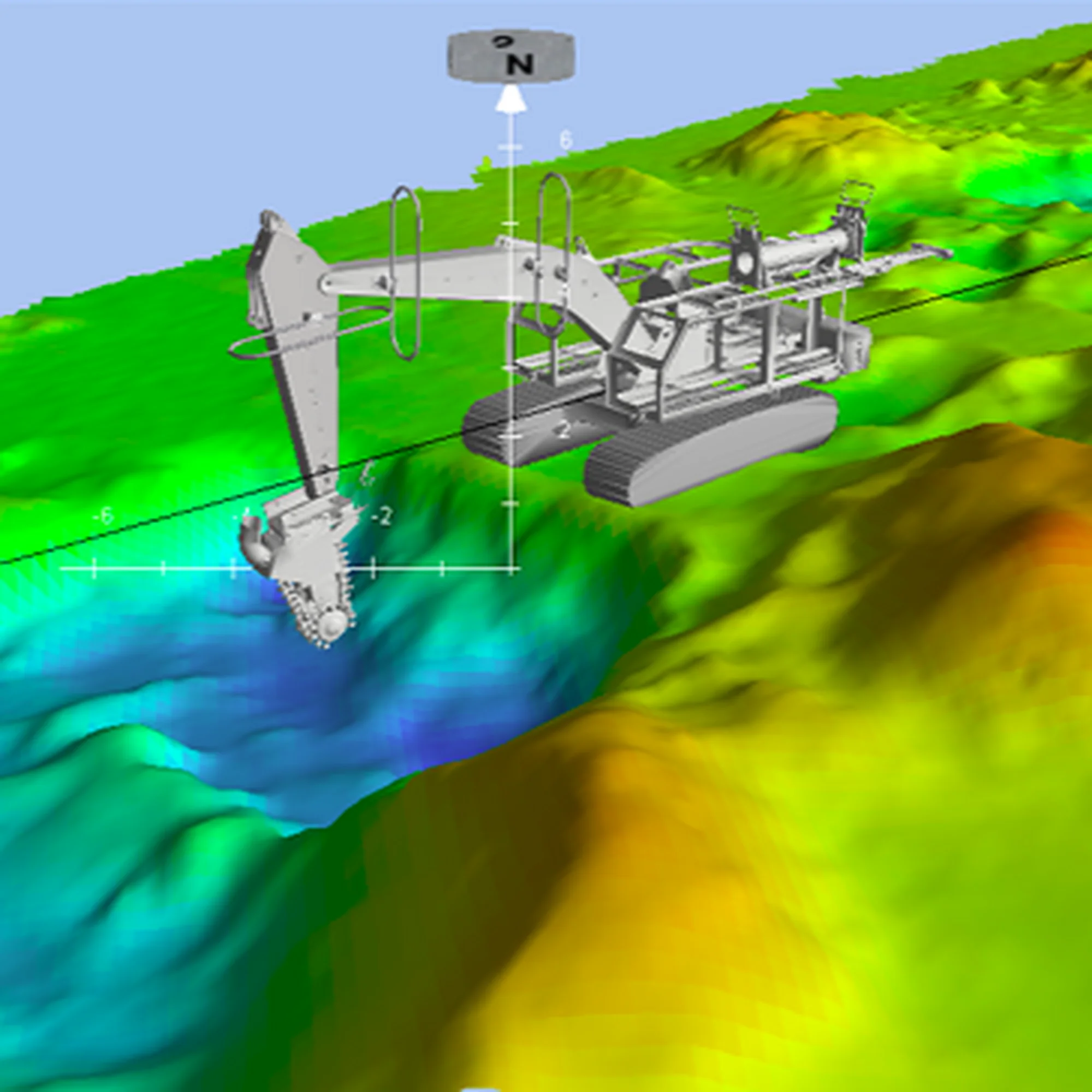
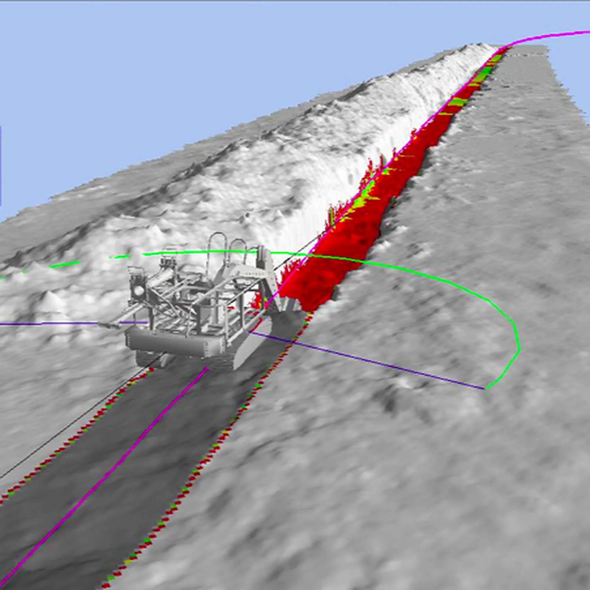
PDS 3D live monitoring with real-time terrain models, integrated with vessel survey and positioning systems.
Real-time multibeam echo sounder data and post-survey data used to assess trench performance.
Integrated auto-heading, keeping the tool on target regardless of vessel heading.
(SCANCFE9000)
(SM08 with Chain cutter)
Project Execution
In Phase 1, the seabed proved to be a heterogeneous mix of hard clay, limestone and large rocks. Suction and chain cutting were ineffective, while an excavation bucket with water-jet supply proved the most effective and reliable tool. Optimising the trench design from 6 m with slopes to 4 m without slopes reduced the design volume by two-thirds.
In Phase 2, SCANCFE 9000 operated without equipment downtime on its first deployment, demonstrating the new system’s operational reliability.
For the 26-inch pipeline, Scanmudring trenched 30 km of the 38 km route and relocated approximately 208,000 m³ of material. 8.6 km remained untrenched because the route included restricted-access areas, crossings, shallow-water sections and non-removable hard seabed. 3.8 km consisted of very hard material, for which the client selected concrete mattresses as the alternative protection solution.
The 6.3 km umbilical scope achieved 100% completion, with 36,000 m³ of material relocated. SCANCFE 9000 was also used to mechanically backfill four selected cross-sections of 100 m each on the 26-inch pipeline, totalling 0.4 km, to support the installation of concrete mattresses.
(SCANCFE9000 Phase 2)
(SM08 Phase 1)
Adapting to the seabed
The most demanding aspect of the campaign was the variation between extremely hard seabed and rapidly moving loose sand. In selected sections of the 26-inch route, consolidated coral and sandstone limited progress even after repeated passes. The team reduced vessel speed and applied multiple cutting passes. A focused 1-metre section approach was also trialled, holding the vessel stationary or at minimum speed while the nozzles worked one metre at a time until the hard layer was penetrated. SCANCFE 9000 progressed through parts of these sections, while the remaining non-removable areas were assigned an alternative protection solution.
A new feature of SCANCFE 9000 was its remotely adjustable outlet nozzles. The technology allowed the team to optimise the flow direction to remove harder seabed material than conventional controlled-flow excavators can typically handle.
In areas of loose sand, real-time multibeam echo sounder data showed trench depths averaging 2.2 m. However, the sand flowed rapidly back into the trench, reducing the achieved pipeline lowering before the post-survey. Scanmudring adapted the method by introducing a higher-speed Flush Pass at 3–5 m/min, combined with tilted 1.0 m outlet nozzles. The increased turbulence delayed the natural backfill and gave the pipeline more time to settle into the trench.
Learning from the initial trials led to a change from 0.8 m to 1.0 m outlet nozzles and an optimised nozzle orientation. Across the documented trial sections, compliance improved from 25% to 70%, from about 53% to 78%, and from 11% to 94%. The final two sections achieved an average top-of-pipe cover of 0.9 m after the Flush Pass.
Conclusion / Lessons Learned
Scanmudring delivered the project with no non-conformance reports, observations or improvement notices in the client’s system, and the SCANCFE 9000 ran its first deployment with no equipment downtime. The 16-inch pipeline and umbilical scopes were completed in full, 30 km of the 26-inch route was trenched, and a documented 280,500 m³ of material was relocated across Phase 2.
The campaign confirmed that controlled flow excavation can handle far more than sand when the method is adapted in real time. In Phase 1, switching to a water-jet bucket and redesigning the trench profile cut excavation volume by two-thirds. In Phase 2, adjusting speed, passes and nozzle settings, including a high-speed flush pass against rapid backfill, raised trial compliance from as low as 11% to 94%. Live 3D monitoring, auto-heading and remotely adjustable nozzles made those adjustments possible.
For future projects, the combined SCANCFE 9000 and Scanmachine 40Te spread gives one crew and one topside system for seabed conditions ranging from loose sand to limestone and coral, reducing mobilisation and vessel changes for the client.